
How to Install J-Channel Around Windows for Drainage
Use the bottom-sides-top sequence, size pieces from the J-channel face width, fold tabs for downward drainage, and leave vinyl free to move.
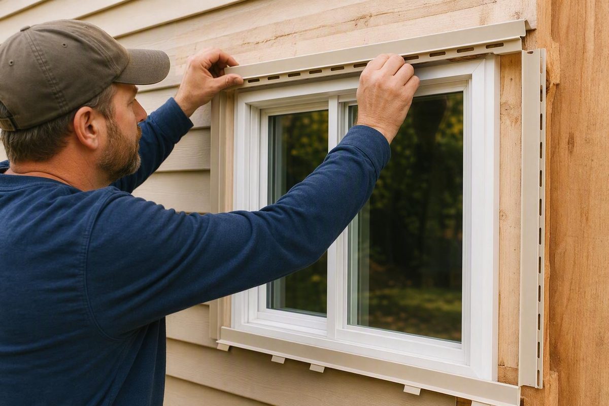
For J-channel used with vinyl siding, the water-shedding sequence is bottom piece first, side pieces second, and top piece last. The bottom tabs fold upward behind the sides; the top tabs extend down into the side-channel recesses. J-channel receives and conceals cut siding edges, but this overview does not establish a complete window-flashing or water-resistive-barrier detail. The instructions for the selected window, siding, and accessory products control.
The short answer: bottom, sides, then top
Install the four pieces in this order:
- Bottom horizontal J-channel
- Both vertical side pieces
- Top horizontal J-channel
This sequence creates downward-shedding corner laps. Tabs retained on the bottom piece turn upward beside the window and finish behind the side channels. Tabs retained on the top piece extend down into those side channels, providing a route from the upper channel into the vertical channels and toward the bottom assembly.1
J-channel is edge trim. Its recess receives and conceals the cut ends of vinyl siding around an opening. A finished J-channel border does not, by itself, establish that the underlying window and drainage-plane details are correct.
Scope of this overview
The window-specific measuring, cutting, and lapping sequence below is the method documented by Fine Homebuilding. The available manufacturer guidance supports the general requirement to keep vinyl accessories straight and able to move, but it does not provide a window-specific cutting diagram. Before cutting, compare this method with the instructions for the exact J-channel profile, siding, window, and flashing assembly. If those instructions conflict, follow the selected manufacturers’ details.
Check the window detail and gather the tools
Identify the window model and examine the opening before measuring the trim. Do not add separate J-channel automatically when the window instructions call for a different receiver.
Inspect visible flashing before trim conceals it. This article does not provide a complete flashing or water-resistive-barrier sequence. If flashing is missing, damaged, or difficult to identify, stop and obtain the applicable window and siding details or qualified help.
The cited window-trimming method places the top J-channel over an existing drip cap. Use that arrangement only when it is compatible with the instructions for the actual window, flashing, siding, and accessory products.
Gather:
- J-channel matched to the selected vinyl siding
- Tape measure
- Square and fine marking tool
- Aviation snips or a suitable saw
- Fasteners approved for the selected accessory and substrate
- Protective equipment required by the cutting-tool instructions
The cited method uses roofing nails, but that does not make roofing nails a universal choice.
Confirm the J-channel’s profile, face width, color, and recess depth before cutting all four pieces. Do not borrow dimensions or fastening rules written for starter strips, cornerposts, or inside-corner accessories.
Measure each piece from the J-channel face width
The face width is the visible width of the J-channel. In the cited method, that width also determines the material allowed at each end to create the corner tabs.
Let:
- O = measured opening dimension
- F = measured J-channel face width
- L = starting length of a tabbed piece
The starting formula is:
L = O + 2F
Thus, a 36-inch opening with a 1-inch J-channel face produces a starting length of approximately 38 inches:
36 in. + 2(1 in.) = 38 in.
The commonly stated 2-inch total addition is only an example based on a face approximately 1 inch wide. It is not a universal allowance.1
Use the same principle for the applicable vertical opening measurement: add twice the actual face width before preparing the ends.
The top and bottom pieces retain material at both ends to form tabs. Corresponding end material is removed from the side pieces.
Conceptual cut-and-lap diagram—not a cutting template or flashing detail:
J-CHANNEL PROFILE — identify these parts on the actual product

      visible face
          │
          ▼
       ┌──────┐
       │      └───┐  ← recess that receives the siding edge
       │          │
───────┴──────────┘
   nail hem / fastening leg


HORIZONTAL PIECE — TOP OR BOTTOM

      retained end tab       opening span       retained end tab
             │                                      │
             ▼                                      ▼
      |<-- F -->|<-------------------------->|<-- F -->|
      ┆ CUT LINE ┆                            ┆ CUT LINE ┆
      ┌──────────┬────────────────────────────┬──────────┐
      │  RETAIN  │         J-CHANNEL          │  RETAIN  │
      └──────────┴────────────────────────────┴──────────┘

      Bottom tabs fold UP behind the side channels.
      Top tabs extend DOWN into the side-channel recesses.


VERTICAL SIDE PIECE

      ┌──────────────┐
      │ REMOVE END   │  ← material corresponding to the tab area
      ├──────────────┤
      │              │
      │ SIDE CHANNEL │
      │              │
      ├──────────────┤
      │ REMOVE END   │  ← material corresponding to the tab area
      └──────────────┘
This diagram shows the intended retained and removed areas, not the exact cuts through every wall of every J-channel profile. The available window-specific source says to cut along the inside of the channel by the face width, but it does not identify every profile surface in enough detail to serve as a universal cutting template. Use the selected accessory’s cut diagram to determine precisely which walls, face portions, or nail-hem sections must be cut.
Mark and test-fit one piece before preparing the other three. This can reveal an incorrect face-width assumption or reversed fold direction before more material is lost.
Cut and install the four pieces
The following is a qualified overview of the cited method, not a substitute for a profile-specific cutting illustration.
-
Prepare the bottom piece. At each end, measure inward by one face width. The cited method calls for cutting along the inside of the channel while retaining the end material needed for a tab. Do not proceed until the selected product detail makes clear which parts of its profile are cut and which remain attached.
-
Position the bottom. Center the piece beneath the opening and keep it straight. Fasten it through the designated fastening area using the selected accessory’s approved fasteners and fastening pattern.
-
Fold the bottom tabs upward. Turn each retained tab up beside the window. The tabs must finish behind the vertical side channels.
Checkpoint: Each lower lap should direct drainage toward the bottom assembly rather than behind the siding.
- Prepare and position the side pieces. Remove the corresponding end-tab material specified by the profile’s cutting detail. Place each side channel over the upward-folded bottom tab, keep the piece plumb, and fasten it without pinching the vinyl.
Checkpoint: At each lower corner, the side channel should cover the bottom tab while preserving the intended downward route.
- Prepare and position the top piece. Retain tabs at both ends according to the product’s cut detail. Install the top last, extending each tab down into the recess of the corresponding side channel.
Checkpoint: The upper laps should direct water entering the top channel into the side-channel recesses rather than behind them.
The Fine Homebuilding method fastens the bottom J-channel with roofing nails at approximately 12-inch intervals. Treat that only as the cited method—not as a universal code or manufacturer requirement. Use the fastener type, spacing, penetration, and placement required for the selected accessory and substrate.1
Where a drip cap already exists, use the relevant product details to determine whether the top J-channel belongs over it and how the two components should relate.
Fasten the channel without locking the vinyl in place
Keep every piece straight while fastening.
Vinyl accessories need room for temperature-related movement. CertainTeed applies its general vinyl cutting, nailing, and expansion principles to accessories such as J-channel and says accessories should remain straight while being able to move as temperatures change.2 Do not drive fasteners so tightly that they distort or clamp the fastening area.
Check the selected J-channel instructions for:
- Approved fastener material and type
- Required penetration into the substrate
- Placement within the designated slots or fastening area
- Fastener spacing
- Required clearance beneath the fastener head
- Expansion allowance for the piece length and installation conditions
After fastening, sight along each channel. It should remain straight, and its fastening area should not be pinched or distorted.
Do not apply CertainTeed’s published starter-strip spacing, cornerpost clearance, or inside-corner dimensions to window J-channel. Those measurements address different accessories and conditions.
Fit the siding below the window and choose the right receiver
This section explains the supported vertical measurement and receiver choice. It does not establish the complete notch width, cut-transfer method, or retention detail for every siding profile.
For the siding course beneath the window, the cited method measures from the lower course’s buttlock to the top of the J-channel recess, then deducts approximately 1/4 inch for expansion.1
A lengthwise cut beneath the window may remove the panel’s factory nail flange. Undersill trim may retain the remaining cut edge when that edge fits the trim securely. It may not grip adequately if the cut crosses a thicker center or lower portion of the siding profile.
Choose the receiver by the cut and window detail
- J-channel: Use it to receive and conceal a compatible cut siding edge.
- Undersill trim: Consider it when a lengthwise cut removes the nail hem and leaves an edge the trim can grip securely.
- Integral window receiver: Follow the window instructions rather than adding separate trim by default.
If the nail hem has been removed and the available product instructions do not show how to retain that specific cut edge, stop before covering the opening. Do not assume that either J-channel or undersill trim will secure every siding profile.
Before installing the surrounding siding, inspect the assembly:
- The bottom and top channels are straight.
- Both side channels are plumb.
- Bottom tabs turn upward behind the side channels.
- Top tabs enter the side-channel recesses.
- Corner laps are oriented for downward drainage.
- Fasteners do not clamp or distort the vinyl.
- Channel recesses remain unobstructed.
- Cut siding has a compatible, secure receiver.
- The trim arrangement agrees with the selected window and siding details.
The practical rule is to measure from the actual J-channel face, work from bottom to top, orient the tabs for downward drainage, and leave the vinyl free to move. If the flashing arrangement, integral receiver, fastening requirements, exact profile cuts, or cut-panel retention remains unclear, use the applicable manufacturer detail rather than treating this generic trim method as a complete waterproofing specification.